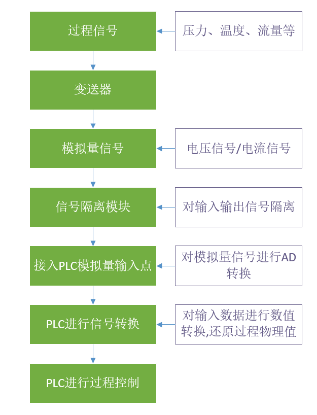
Analog signal is the most basic input form of process signal (pressure, temperature, flow, etc.) in automatic process control system. The process signals in the system are converted into unified voltage and current signals through the transmitter, and these signals are transmitted to the controller (PLC) in real time.
PLC converts these analog signals into internal numerical signals through calculation conversion. So as to realize the monitoring and control of the system. From the physical signal on the site to the numerical signal processed inside the PLC, there are the following steps:
From the above signal input process of PLC analog quantity, we can see that the input of analog quantity signal is very complex in the automatic process control system. However, in the current industrial field, analog signal processing has basically adopted current signal mode for transmission. Compared with voltage signal mode, current signal has stronger anti-interference ability, longer transmission distance and stable signal.
Here is a simple decomposition of the conversion process of analog signals by PLC.
1. After the analog signal is connected to the PLC, the PLC converts the analog signal into integer data, not floating point number (e.g. Siemens – 27648 to 27648);
2. The analog conversion range of different brands of PLC is different (for example, Siemens – 27648 to 27648; Delta – 32384 to 32384);
3. The conversion range of the same PLC module to different types of analog signals is consistent (for example, the conversion range of Siemens to ± 10 V, ± 5 V, ± 2.5 V or 0 to 20 mA analog signals is – 27648 to 27648);
Therefore, from the above points, we can know that the analog signal connected to the PLC needs to be re-converted before the data matching the actual physical quantity can be obtained; When performing data conversion processing, it should also correspond to the processing data range of the PLC module used.
PLC data conversion process
Post time: Feb-15-2023


